Layout and Connectors
Sensor ID-lookup
| Sensor ID | Sensor function | Short name | OC port | IC voltage (high) | Pull-down resistor |
|---|---|---|---|---|---|
| Sensor 0 | UART 2 | u2 | oc7 | 2.7 - 5 V | |
| Sensor 1 | RS232 1 | r1 | oc7 | 4.6 - 5.7 V | R33 |
| Sensor 2 | RS422 | r4 | oc4 | 2.7 - 5 V | |
| Sensor 3 | UART 3 | u3 | oc4 | 4.6 - 5.7 V | R35 |
| Sensor 4 | UART 1 | u1 | oc4 | 2.7 - 5 V | |
| Sensor 5 | RS232 2 | r2 | oc4 | 4.6 - 5.7 V | R31 |
| Sensor 6 | SPI 1 | s1 | oc2 | 2.7 - 5 V | |
| Sensor 7 | SPI 2 | s2 | oc1 | 2.7 - 3.3 V | |
| Sensor 8 | IC only | only | 4.6 - 5.7 V | R44 | |
| Ext. Trig | trig | oc3 |
To change the IC High voltage from 4.6 - 5.7 V to 2.7 - 3.3 V, remove the indicated pull-down resistor. Do not exceed the maximum of these voltages.
Connector info
The cables that are used with the primary ports of the SentiBoard are the Samtec Micro Mate™ S1SD-05 series. The breakout boards are designed to use the -L1 (Pin 1 to pin 1) configuration.
The connectors on the SentiBoard are the Samtec Micro Mate™ T1M-05-GF-DH.
Secondary connector
The 2-pin connectors on the SentiBoard are the Molex Micro-Lock Plus 205957-0271. This mates with the 204532-0201. Pin 1 is used as ground and Pin 2 is used as signal.
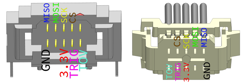
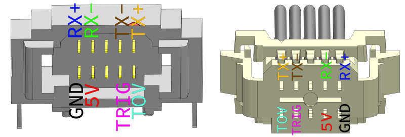
Sensor Ports Connector Specification
This sections shows the connector specification, as well as describing for sensor which signal SentiSystems have utilized in order to ensure proper synchronization of the payload's sensor data.
The names are as seen from the SentiBoard. That is, the TX is connected to the TX pin on the SentiBoard, and thus is the pin where the SentiBoard transmits data to the sensor. This should be connected to RX pin of the connected device.
UART
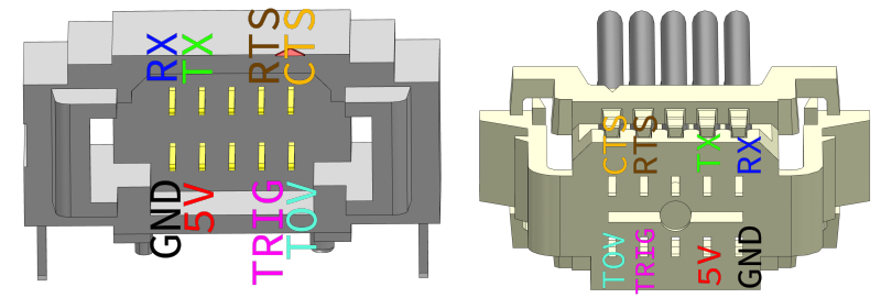
RS-232
RS422
SPI